


Views: 0 Author: Site Editor Publish Time: 2026-09-27 Origin: Site


Industrial facilities frequently manage high-volume, low-concentration exhaust streams. Routing these streams directly into a thermal oxidizer introduces a major operational problem. Operators face exorbitant supplemental fuel requirements just to maintain combustion temperatures. The solution involves a carefully engineered architecture. A properly integrated VOC Concentrator Unit transforms high-volume, low-concentration emissions into low-volume, high-concentration streams. This process drastically reduces the required oxidizer size and slashes fuel demand.
However, the stakes remain incredibly high during system design. Poor layout integration between pretreatment stages, the rotor, and the oxidizer causes massive downstream issues. You might experience premature media failure, thermal inefficiencies, and severe compliance breaches. This guide breaks down how to evaluate your setup. We will explore ways to specify a cohesive system architecture. You will learn to integrate these components safely, ensuring long-term operational stability and maximum destruction efficiency.
VOC pretreatment is non-negotiable; inadequate filtration or temperature control will permanently blind or damage the zeolite rotor.
Targeting the correct concentration ratio (typically 10:1 to 30:1) minimizes the required oxidizer capacity and operational expenditure (OPEX).
Pairing a VOC Concentrator with RTO (Regenerative Thermal Oxidizer) allows for closed-loop thermal recovery, utilizing oxidizer exhaust to heat the desorption stream.
System layout must prioritize Lower Explosive Limit (LEL) safety limits, pressure drop management, and bypass capabilities during process fluctuations.
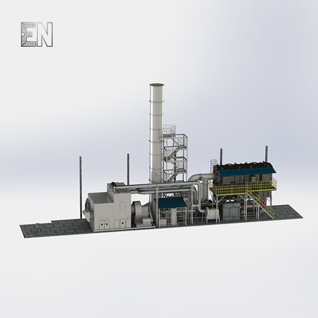
Purchasing standalone environmental control components rarely yields expected efficiencies. Operators often buy a concentrator from one vendor and an oxidizer from another. They then expect seamless operation. Unfortunately, this fragmented approach usually fails. You must engineer the entire layout as a single thermodynamic and pneumatic loop. The system acts like an interconnected lung. Every pressure change or temperature fluctuation in one section directly impacts the others.
To measure success, you need clear criteria. A well-integrated architecture achieves 95% to 99%+ overall Destruction and Removal Efficiency (DRE). Simultaneously, it must sustain auto-thermal operation. Auto-thermal operation means the system requires zero supplemental fuel once it reaches a steady state. The concentrated volatile organic compounds provide enough calorific value to maintain the oxidizer's combustion temperatures.
A cohesive layout relies on several core components working in unison. You must seamlessly connect these elements:
Process Exhaust Fan & Ducting: These components manage pressure drops across the entire network. Undersized fans create dangerous bottlenecks in production areas.
Conditioning/Pretreatment Skid: This section controls temperature and captures particulates before air reaches the rotor.
Rotary Concentrator: The central hub containing the adsorption, desorption, and cooling zones.
Combustion Unit & Heat Exchangers: The oxidizer destroys the pollutants. Meanwhile, heat exchangers recover thermal energy to drive the desorption cycle.
Failure to balance these four components leads to unstable airflow. When airflow fluctuates, concentration ratios drop. Consequently, the oxidizer consumes massive amounts of natural gas to compensate for the lost calorific value.
You must establish a robust defense line before dirty air ever touches the concentrator wheel. The objective is simple but critical. You must protect the expensive zeolite matrix from masking, plugging, and thermal degradation. Proper VOC pretreatment ensures the rotor maintains its structural integrity and adsorption capacity over a long lifespan.
Engineers must carefully evaluate several key design parameters and risks during this stage. Ignoring these parameters guarantees premature system failure.
Zeolite substrates adsorb poorly when temperatures exceed 40°C (104°F). Process streams coming from ovens or drying lines often exceed this threshold. Therefore, you must integrate cooling coils into the ducting layout. These coils drop the airstream temperature into an optimal adsorption range.
Relative Humidity (RH) presents another significant challenge. You must keep RH below 80%. Water vapor aggressively competes with volatile organic compounds for the limited adsorption sites within the zeolite pores. High humidity levels will displace the targeted pollutants, sending untreated emissions straight out the exhaust stack. Planners often use cooling and subsequent slight reheating to drop the relative humidity into a safe zone.
Particulate blinding destroys concentrator wheels quickly. You must implement multi-stage filtration. A common layout features a G4 pre-filter followed by rigid F7 or F9 filters. This sequence captures airborne dust and aerosols before they can physically plug the honeycomb structure of the rotor.
Finally, you must address high-boiler risks. Compounds boasting boiling points above 200°C (such as heavy resins, plasticizers, and complex polymers) introduce severe complications. They stick to the zeolite but refuse to release during the standard desorption cycle. These high-boilers permanently occupy the adsorption sites. Over time, the wheel loses its functional capacity. If your process emits these heavy compounds, you must install specialized guard beds or condensation traps upstream.
Design Parameters for Optimal Air Stream Conditioning
Parameter | Target Range | Risk if Ignored | Required Layout Component |
|---|---|---|---|
Temperature | Under 40°C (104°F) | Zeolite loses ability to capture pollutants | Chilled water cooling coils |
Relative Humidity (RH) | Below 80% | Moisture occupies adsorption sites | Dehumidification or trim heaters |
Particulates | >99% removal of fine dust | Physical plugging of honeycomb matrix | Multi-stage G4 to F9 rigid filters |
High-Boiling Compounds | Near zero entering wheel | Permanent blinding of zeolite media | Sacrificial guard beds |
Understanding the internal mechanisms of the VOC Concentrator helps you optimize the surrounding layout. The core technology relies on a rotating hydrophobic zeolite wheel. This wheel continuously processes the factory airstream through three distinct isolated zones.
The vast majority of the wheel's surface area serves as the adsorption zone. The pretreated, cool, and filtered process air passes through this section. The hydrophobic zeolite aggressively strips the volatile organic compounds from the air. Clean air then exits the back of the wheel and releases directly to the atmosphere. You must size your main process fan to handle the specific pressure drop across this deep honeycomb structure.
As the wheel rotates, the saturated zeolite enters the desorption zone. Here, the system extracts the trapped pollutants. A separate, much smaller airstream routes through this isolated wedge. This desorption stream represents just 1/10th to 1/20th the volume of the main process air. The system heats this small air volume to temperatures between 180°C and 220°C (350°F–430°F).
When this intensely hot air hits the zeolite, it breaks the molecular bonds holding the pollutants. The volatile compounds release into this low-volume air stream. You now have a highly concentrated exhaust ready for efficient combustion. Maintaining tight seals around the desorption zone is crucial. Leakage here ruins the concentration ratio and sends dirty air back into the clean stream.
The heated zeolite cannot immediately return to the adsorption phase. Hot zeolite cannot capture pollutants effectively. Therefore, the wheel rotates into a dedicated cooling zone. Ambient or freshly purified air passes through this section. This airflow rapidly cools the wheel matrix. The cooling process restores the adsorption capacity and prevents spontaneous combustion within the ductwork. Once cooled, the section rotates back into the main adsorption zone, completing the continuous cycle.
Once you extract and concentrate the pollutants, you must destroy them safely. Your layout choice for the combustion unit depends heavily on pollutant type and your energy recovery goals. Engineers typically choose between three distinct solution categories.
For most industrial applications, pairing a VOC Concentrator with RTO (Regenerative Thermal Oxidizer) provides the most robust solution. An RTO utilizes ceramic media beds to capture and reuse heat. It easily offers up to 95% primary thermal energy recovery.
The true integration advantage lies in the closed-loop thermal design. You can route the RTO’s clean, hot exhaust through a secondary heat exchanger. This exchanger transfers thermal energy directly into the concentrator's desorption air stream. By harvesting waste heat from the oxidizer, you completely eliminate the need for an independent electric or gas heater for the desorption cycle. This creates a highly efficient, self-sustaining loop.
Some layouts utilize Catalytic Recuperative Oxidizers instead of RTOs. These systems work best for applications emitting clean, highly specific compounds. They operate at much lower temperatures, typically between 250°C and 300°C. The lower temperature reduces thermal stress on the surrounding ductwork.
However, catalytic systems carry significant risk. They remain highly susceptible to catalyst poisoning. Heavy metals, sulfur, and silicone derivatives will permanently deactivate the precious metal catalyst beds. If your manufacturing process introduces any masking agents, the catalytic layout will fail rapidly. You must perform rigorous chemical profiling before selecting this route.
Direct Fired Thermal Oxidizers represent a simpler alternative. Facilities select DFTOs for extremely high concentration streams. If your concentrated exhaust approaches 25% of the Lower Explosive Limit (LEL), a DFTO handles the load safely. This layout prioritizes lower upfront capital costs over long-term fuel efficiency. DFTOs lack the extensive heat recovery media found in RTOs. Consequently, they consume more supplemental fuel if the pollutant concentration drops unexpectedly during process slowdowns.
You must evaluate layout specifications based on concrete operational outcomes. Haphazardly placing equipment across a factory roof leads to maintenance nightmares and safety hazards. Use these authoritative lenses to specify your system architecture.
First, analyze the physical footprint and modularity. Determine whether the system should be skid-mounted or built-in-place. Skid-mounted systems arrive pre-wired and pre-piped. They offer easier installation and faster commissioning. However, built-in-place layouts work better for facilities facing strict spatial constraints or requiring complex duct routing around existing infrastructure.
Next, focus on concentration ratio matching. Ensure your engineering team aggressively optimizes the ratio. A high ratio minimizes the required oxidizer size. Yet, you must never push the desorbed stream dangerously close to explosion thresholds. The standard safety limit dictates keeping the concentrated stream strictly below 25% LEL. Pushing a 30:1 ratio on an already volatile airstream risks severe deflagration.
Authoritative engineering demands rigorous safety integration. You must mandate continuous LEL monitors within the ducting between the concentrator and the oxidizer. These sensors act as the nervous system of your layout.
Additionally, integrate automatic fresh-air bleed valves. If the LEL monitor detects a sudden spike in concentration, these valves instantly open. They introduce ambient dilution air, rapidly dropping the concentration back to safe levels. You also need fail-safe bypass dampers. If a thermal event occurs, these dampers trigger immediately. They either route process air directly to the atmosphere (if local environmental permits allow emergency venting) or safely isolate and shut down the entire exhaust network.
Evaluate your equipment vendors critically. Look for transparent performance guarantees. Trustworthy integrators explicitly state the required pretreatment conditions necessary to maintain their DRE guarantee. They will clearly document projected pressure drops across every filter bank, rotor, and heat exchanger. Avoid vendors who offer generic performance claims without requiring a detailed chemical analysis of your specific exhaust stream.
Real-world implementations often reveal gaps between theoretical engineering and factory-floor realities. Learning from common rollout mistakes ensures your integration proceeds smoothly.
Underestimating the cumulative pressure drop represents the most frequent rollout failure. Engineers sometimes calculate the pressure resistance of the rotor but forget the compounding resistance of the ductwork, pretreatment filters, and heat exchangers. This miscalculation leads to under-sized process fans. When the fan cannot pull enough vacuum, exhaust backs up into the production facility. This bottleneck forces operators to slow down manufacturing lines to prevent indoor air quality hazards.
Maintenance planning must dictate layout choices. Rotor seals degrade over time due to constant friction and high temperatures. These seals prevent cross-leakage between the dirty adsorption zone and the highly concentrated desorption zone. If seals fail, DRE plummets. When specifying your unit, demand high-quality, easily replaceable silicone or specialized fluoroelastomer seals. Ensure the physical layout provides technicians with easy access doors to inspect and replace these seals without dismantling major ductwork.
Follow a strict progression when finalizing your layout strategy. Do not skip these fundamental steps:
Conduct a comprehensive characterization study of your exhaust. Document the speciation, precise concentration variations, maximum temperatures, and particulate loads.
Request detailed Piping and Instrumentation Diagrams (P&IDs) from multiple vendors. Carefully evaluate how effectively they design the heat recovery loop between the oxidizer and the desorption heater.
Evaluate system longevity and routine maintenance intervals across a 10-year horizon. Prioritize long-term reliability and robust media protection over initial setup convenience.
A tightly integrated pretreatment-rotor-oxidizer layout delivers immense strategic value. It bridges the gap between environmental compliance and operational efficiency. By transforming high-volume, low-concentration exhaust into manageable streams, facilities achieve maximum pollutant destruction without burning massive amounts of supplemental fuel.
Do not treat the concentrator, the filters, and the oxidizer as siloed purchases. Their performance relies entirely on pneumatic and thermodynamic balance. Partner strictly with integrators who engineer the entire loop. They must guarantee the destruction efficiency and operational stability of the combined system, not just individual parts.
Take proactive measures today. Initiate a thorough process airstream analysis to map your exact emission profile. Request a custom layout consultation from specialized integration engineers to ensure your facility remains safe, compliant, and highly efficient.
A: With optimal pretreatment, a zeolite wheel can last 7 to 10 years. You must maintain strict temperature and particulate control. Poor pretreatment can reduce this lifespan to less than 2 years due to permanent masking, heavy resin buildup, or severe thermal damage.
A: An RTO handles a much wider variety of volatile compounds without the risk of catalyst poisoning. It offers superior thermal heat recovery. This closed-loop efficiency makes the RTO far more robust and adaptable for fluctuating industrial manufacturing processes.
A: Properly designed layouts incorporate continuous LEL monitors. If concentrations approach critical safety limits (typically 25% LEL), the system automatically reacts. It will introduce fresh dilution air or trigger a safe emergency bypass. This immediate response prevents dangerous deflagration inside the oxidizer.


